
The aim of this article is to analyse the machining parameters calculation for basic turning operations. In case that you have not read our previous article that explains the basics on machining parameters and discusses their selection, it will be better to read it now by clicking this link as the present article is based on that.
Nevertheless, the simplified 2D approach to machining processes, which was discussed last time, is to be reminded. Based on the basic chip formation mechanism, the main machining parameters are the Cutting Speed (VC) and the initial chip thickness (t0) and these define the programmed speed of the spindle (RPM) and feedrate of the cutting tool (mm/min). Next, the basic 2D chip formation model will be connected with the basic geometry of the cutting region during turning so as to better understand the programming of the relevant speeds and feeds.
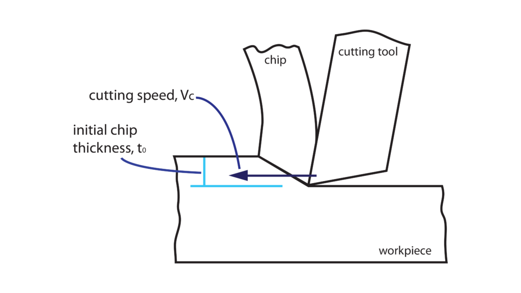
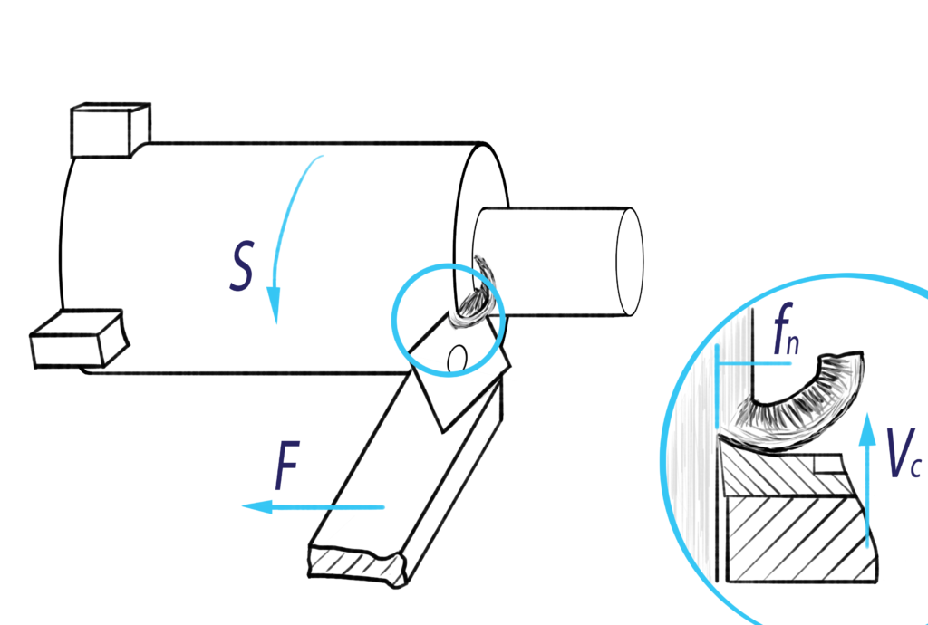
Overviewing turning process, it can be said that chip formation occurs because a relatively stationary cutting tool which has a main cutting edge collides with the revolving part which is attached to the lathe spindle. This implies that the cutting speed that is required to initiate the chip formation process is the result of the relative speed of the stationary tool against the rotating part. Understanding this relative motion and observing the turning procedure from the right perspective, we can conclude that the chip formation process during turning directly reflects to the basic model that has been already analysed. Thus, it can be realized that the cutting speed of the basic chip formation model is directly related to the rotational speed of the spindle and thus the linear speed of the workpiece surface at the active machining diameter. This is why the cutting speed is also named as surface speed for turning operations.
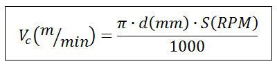
Based on the previous assumptions and realisations, we can define the relation between the rotational speed of the workpiece and the cutting speed that the cutting tool is to face. This is to define the formula that connects the cutting speed of the turning process when the cutting tool removes material on a specific diameter and the workpiece rotates around its axis at a programmed rotational speed (RPM). Thus, if we start our analysis by defining the formula that governs the simple rotational motion and transform it so as to use more machinist friendly units, we get the following:
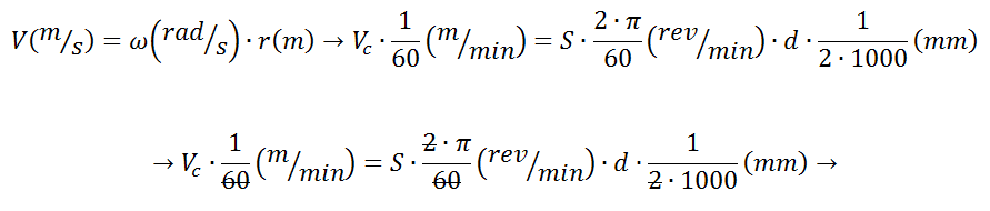
Where
S: the programmed rotational speed of the machine tool spindle in RPM
VC: the cutting speed in m⁄min, as it is suggested by the relevant combination of cutting tool the workpiece material and any other parameter has been already discussed here.
d: the final diameter of the part in mm
or if we solve the formula so as to get the rotational speed of the spindle:

The last formula indicates that the spindle speed has to change every time that the active machining diameter changes. This is a usual requirement so as to ensure that the cutting speed will be constant and the machining process will produce almost the same results for different diameters. The need for frequent spindle speed alterations complicates its programming when for example the workpiece geometry is complicated and its diameter changes continuously during turning. Manufacturers of CNC controllers try to manage this issue by offering the selection to directly program the cutting speed by running the procedure of activating the Constant Surface Speed (CSS) turning strategy. Thus, by activating the CSS selection the controller manages the alteration of the spindle speed according to the changes of the active turning diameter.
The best practices regarding the proper activation of Constant Surface Speed will be discussed on an upcoming article.
The next parameter that has to be programmed so as to initiate the turning process is the tool feedrate (F). Feedrate refers to the rate that the cutting tool moves along the surface of the workpiece and can been programmed either in mm/min or in mm/rev.
Observing the geometry of the region that the actual chip removal occurs, we can state that a chip, with an initial thickness of fz, is getting removed due to the relative motion of the tool’s cutting edge against the rotating workpiece. This initial thickness of the chip is directly related with the initial chip thickness of the basic chip formation model t0 and is equal to the distance that the tool feeds forward after a complete rotation of the workpiece.
Thus, the programming of the feedrate in mm/rev implies the direct use of the initial chip thickness value that is given by the cutting tools manufacturers. However, attention should be given as this variation of feedrate programming depends on the spindle speed. So, in practice zero spindle speed results to the halt of the cutting tool motion regardless of the programmed feedrate in mm/rev.
The definition of the feedrate per revolution falls into the restrictions about the initial chip thickness that were discussed on our previous article and the programmer have to make sure that the actual feedrate values are within the acceptable limits.
On the other hand when we program the feedrate in mm/min, the feedrate value has to be calculated by multiplying the feedrate per revolution by the spindle revolutions per minute.
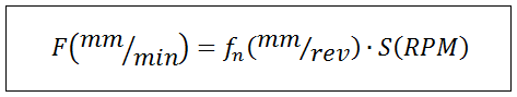
Where:
F: the programmed feedrate in mm⁄min
fn: the feedrate per revolution in mm⁄rev
S: the programmed spindle speed in RPM
The optimal selection of the cutting tool depends on the turning process that we have to undertake and our productivity or accuracy expectations. When we select a cutting tool, the manufacturer always provides the two basic machining parameters, which are the cutting speed and the feedrate per revolution, and we are responsible for the calculation of the best applicable feed and spindle speed by using the provided formulas.
A common speculation is the fact that the manufacturers usually provide a relatively wide value range for the cutting speed and the feedrate per revolution. Thus, the main problem is the selection of the best values for a specific turning process. We are going to reinvestigate this problem in upcoming articles but first we have to discuss and understand the various parameters that are involved to machining operations and how they affect the selection of the optimal machining parameters.
Finally, it has to be mentioned that there are machinists’ calculators that are capable of calculating the speeds and feeds according to the previous formulas. Also, there are numerous smartphone applications that can calculate the machining parameters according to the formulas.
My personal choice is the MechTab application that is free and available for both Android and iOS users.
If you want to stay updated and get informed for our upcoming articles, you can subscribe to our newsletter and we will keep you informed about our new articles and our activities.
Also, do not hesitate to contact us for every question or problem regarding the CNC machining and programming and we will be happy to help you find the best possible solution!