Articles

Conventional vs. Climb Milling

This article is to analyse the basics of milling strategies and more specifically the two variants of peripheral milling. Thus, conventional and climb milling strategies are to be discussed and their pros and cons will be explained so as to make clear when it is better to use the one or the other. It has to be underlined that everything that is to be mentioned refers to peripheral milling.

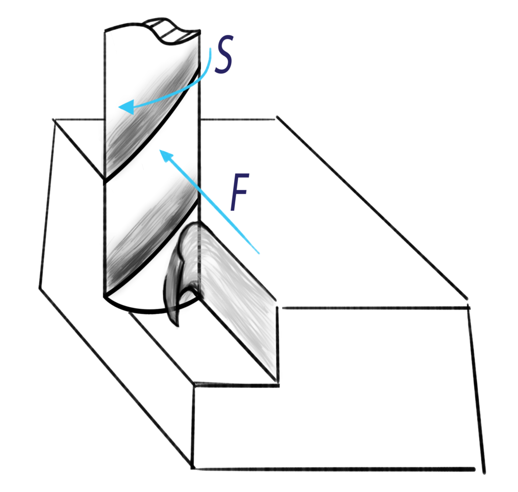
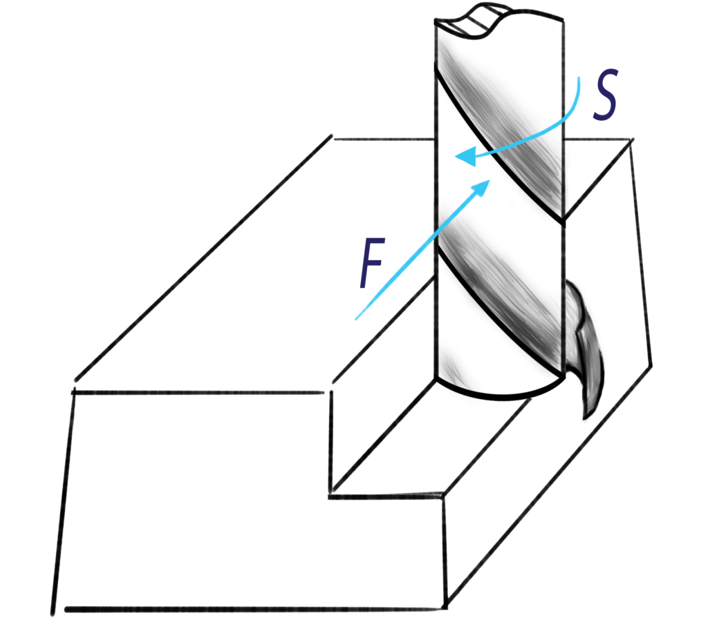
Peripheral milling is considered to be done when the cutting tool removes stock material while being fed in a direction that is perpendicular to its axis of revolution. The way that the rotating tool engages with the stock material and forms the chip is directly related with the machining process and its results. Thus, there are two different strategies for conducting a peripheral milling, namely conventional and climb milling. Next, the advantages and disadvantages of each strategy are to be discussed and analysed.

Conventional Milling

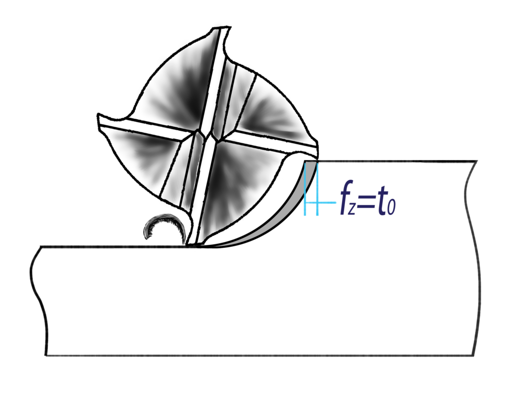
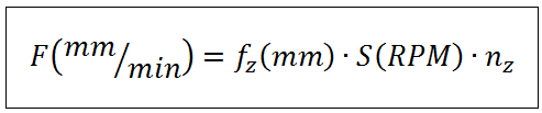
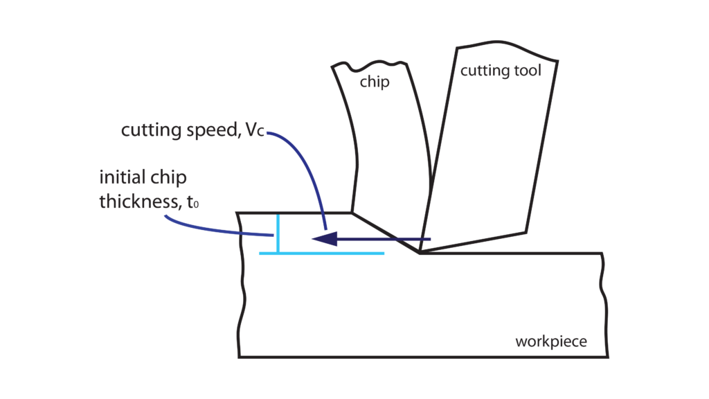
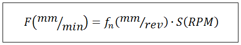
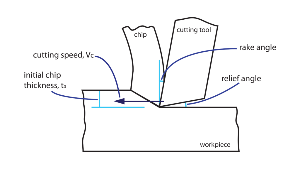
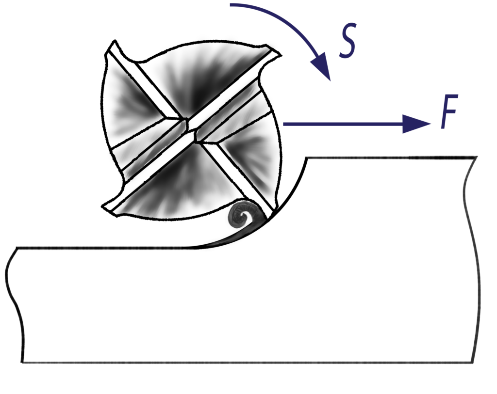
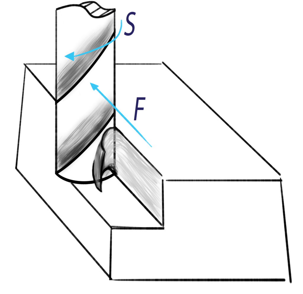
Conventional milling is defined as the machining approach that the vector of the cutting speed has the opposite direction of the workpiece’s relative motion against the tool’s axis of rotation. In that case the cutting tool engages with the workpiece at the maximum width of cut and the chip formation continues up to the unmachined workpiece surface. This indicates that the initial chip thickness, as it has been analysed on previous articles, starts at zero thickness and gradually thickens until it is equal to the feed per tooth of the cutting tool which can be calculated by the active feedrate and the spindle speed.

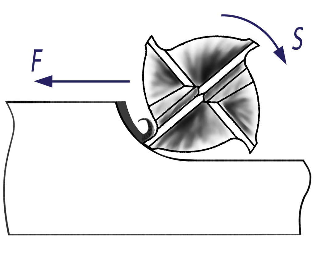
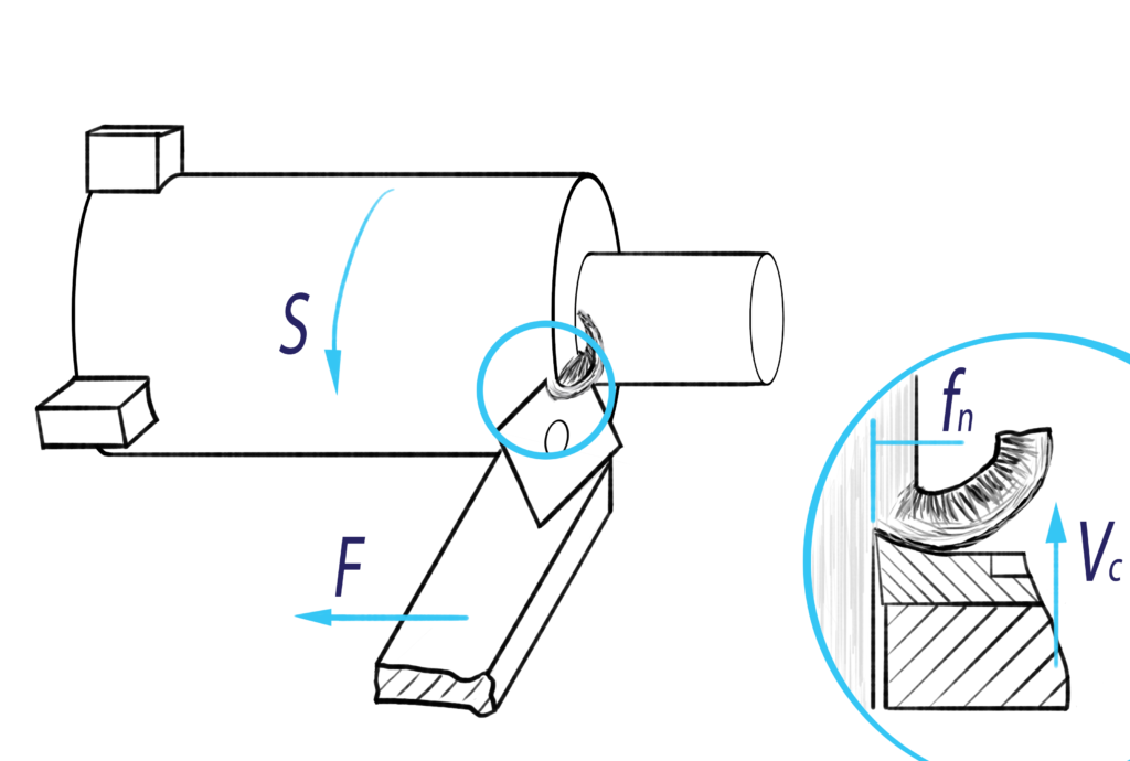
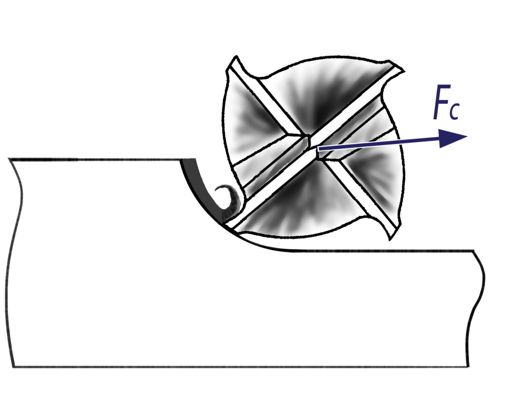
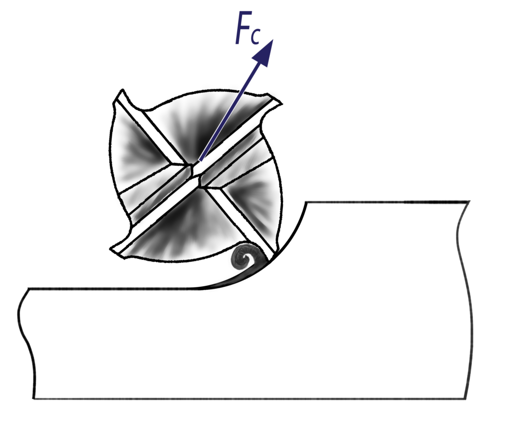
Moreover, this results to the initial rubbing of the cutting tool edges with the material surface until the initial chip thickness is adequate so as to initiate the chip formation process. Also, at the initial stage where the tool edges rub against the workpiece without forming chips, the surface of the workpiece is deformed which can lead to work hardening. Additionally, the elastic recovery of the deformed surface may lead to the violation of the dimensional accuracy of the machining process. However, conventional milling tends to load the tool with forces that are almost parallel to the cutting surface which results to better geometric accuracy. Also, is has to be mentioned that the cutting forces (FC) tend to pull the workpiece towards the axis of the cutting tool which may arise possible issues regarding the work fixturing, ie when surface milling is conducted utilizing horizontal milling machines.

Moreover, a basic characteristic of conventional milling is that the produced chips are pushed in front of the tool and so they tend to interfere with the chip removal process. This results to inferior surface quality of the final machined product due to the poor chip evacuation.

The last well known characteristic of the conventional milling is that the machining procedure is not affected by the machine tool backlash. It has to be mentioned that this machining strategy is called conventional because it is the best fit for old conventional machine tools that has significant axes backlash. It is the direction of the cutting forces that “push” the workpiece towards the same direction that the backlash is being compensated.

Climb Milling

Climb milling is defined as the machining approach that the vector of the cutting speed has the same direction of the workpiece’s relative motion against the tool’s axis of rotation. In that case the cutting tool engages with the surface of the workpiece and continues until the maximum width of cut. This indicates that the initial chip thickness, as it has been analysed on previous articles, starts at the nominal value of the feed per tooth of the cutting tool which can be calculated by the active feedrate and the spindle speed and gradually gets thinner until it becomes equal to zero.

The general direction of the cutting force during climb milling is almost vertical to the machined surface which means that the cutting tools tend to deform out of the machining plane. This may result to poor geometric accuracy of the machined parts that may lead to parts that are out of tolerances. Also, given the general direction of the cutting force it can be stated that during the surface milling of parts on horizontal milling machines, parts are pushed towards the table of the machine tool and this may allow the simplification of the fixturing system. Moreover, the chips that are formed during climb milling are pushed to the opposite direction of tool’s feed and this allows better chip evacuation eliminating the risk of chip remachining and so it produces better surface quality.

Also, it has to be underlined that climb milling is not recommended when machine tools with significant axes backlash are utilized as the cutting forces tend to “push” the workpiece towards the opposite direction that the backlash is being compensated. The application of climb milling on machine tools that are suffer from notable backlash may induce vibrations to the machining procedure that significantly reduce the life of the cutting tools.

Conventional or Climb Milling?

This question is impossible to be answered directly as there are special machining occasions that one strategy can give better results than the other. Thus, the two strategies will be compared and we will try to clarify when is better to utilize each one.

First of all it has to be underlined that regarding the generality of the machining cases, climb milling is usually capable of giving results that are superior to the conventional milling due to the reasons that are analysed next.

During climb milling the cutting tools are directly initiate the chip formation process because the cutting edges engage with the unmachined surface of the part, while in conventional milling they tend to rub against the machined surface until the initial chip thickness is adequately thick to initiate the chip formation process. This results to better tool life expectancy as the cutting edges do not rub before the chip formation. Also, for the same reason no work hardening of the machined surface is possible and the produced parts are characterized by better dimensional accuracy. Moreover the heat that is produced due to the chip formation during the climb milling tends to be better transferred to the generated chips. On the other hand, during conventional milling more generated heat is transferred to the workpiece compared to the climb milling strategy. This combined with everything that has been already mentioned regarding the initial rubbing of the tool against the part surface, result to the higher probability of dimensional inaccuracies. Additionally, these facts indicate that the machine tool energy requirements are lower for the climb milling process. Finally, the produced surface is better than the one produced by conventional milling due to the more effective chip evacuation during the climb milling.

Nevertheless, there are some noteworthy cases that conventional milling can give better results than climb milling. Thus, whenever surface hardened workpieces are to be machined conventional milling should be utilized as according to the basic kinematics of this strategy the cutting edge initiates the chip formation bellow the part’s surface and so the edge do not engage directly with the hardened surface. Also, whenever higher geometric accuracies are required, conventional milling should be utilized at least for the finishing passes as the cutting forces are almost parallel to the feed of the cutting tool which means that the cutting forces do not have great impact to the geometric accuracy of the machining operations. Moreover, for the same reason conventional milling can be beneficial for the machining of thin walled parts as the cutting forces do not lead to great deflection of the workpiece’s thin walls. Finally, conventional milling is almost the only selection when machining is performed utilizing machine tools with significant axes backlash.

To sum up, climb milling is the way to go for the majority of the machining cases as it has more pros than cons. However, we also have to think about the advantages of the conventional milling and utilize it whenever it can provide us with better machining results.

Generally, a suggested machining strategy, that can give very good results considering both the geometric and dimensional accuracies of the machining process, is to utilize the climb milling strategy for the roughing and finishing operations and then to repeat the finishing step by using the conventional milling strategy (or utilizing the climb milling strategy for the roughing and semi-finishing operations and then finishing by using the conventional milling strategy). However, you have to be careful as this strategy can give workpieces that are out of tolerances if the backlash is not properly compensated.

If you want you read more about the cutting forces direction and the deflection of both the cutting tool and the part, you can check the following reference:

If you want to stay updated and get informed for our upcoming articles, you can subscribe to our newsletter and we will keep you informed about our new articles and our activities.

Also, do not hesitate to contact us for every question or problem regarding the CNC machining and programming and we will be happy to help you find the best possible solution!

Machining Parameters Calculation for Milling Operations

The aim of this article is to analyse the machining parameters calculation for basic milling operations. In case that you have not read our previous article that explains the basics on machining parameters and discusses their selection, it will be better to read it now by clicking this link as the present article is based on that.

Nevertheless, the simplified 2D approach to machining processes, which was discussed last time, is to be reminded. Based on the basic chip formation mechanism, the main machining parameters are the Cutting Speed (VC) and the initial chip thickness (t0) and these define the programmed speed of the spindle (RPM) and feedrate of the cutting tool (mm/min).

Next, the basic 2D chip formation model will be connected with the basic geometry of the cutting region during milling so as to better understand the programming of the relevant speeds and feeds.

orthogoniki kopi

Overviewing milling process, it can be said that chip formation occurs because of the cutting edges of the rotating cutting tool collide with the stationary part which is attached to a work holding device. This implies that the cutting speed that is required to initiate the chip formation process is the result of the relative speed of the rotating cutting tool edges against the rotating part. Understanding this relative motion and observing the milling procedure from the right perspective, we can conclude that the chip formation process during milling directly reflects to the basic model that has been already analysed. Thus, it can be realized that the cutting speed of the basic chip formation model is directly related to the rotational speed of the spindle and thus the linear speed of the cutting tool edges due to their rotation around the axis of the spindle.

Based on the previous assumptions and realisations, we can define the relation between the rotational speed of the cutting tool and the cutting speed that each individual edge is to face. This is to define the formula that connects the cutting speed of the milling process when the cutting tool with specified diameter removes material rotating around its axis at a programmed rotational speed (RPM). Thus, if we start our analysis by defining the formula that governs the simple rotational motion and transform it so as to use more machinist friendly units, we get the following:

Where
S: the programmed rotational speed of the machine tool spindle in RPM
VC: the cutting speed in m⁄min, as it is suggested by the relevant combination of cutting tool the workpiece material and any other parameter has been already discussed here.
d: the diameter of the cutting tool in mm

or if we solve the formula so as to get the rotational speed of the spindle:

The two last formulas are of great importance as we have to recalculate the spindle rotational speed every time we change the cutting tool or the machined material.

The second parameter that has to be programmed so as to make the milling possible is the tool feedrate (F). Feedrate, which is programmed in mm/min for milling operations, refers to the linear velocity of the cutting tool axis relatively to the surface of the stationary workpiece. Observing the geometry of the region that the actual chip removal occurs, we can state that a chip, with an initial thickness of , is getting removed due to the relative motion of the rotating tool’s cutting edge against the workpiece. This initial thickness of the chip is directly related with the initial chip thickness of the basic chip formation model  and is equal to the distance that the tool feeds forward between the moments of the engagement of two sequential cutting edges of the tool with the workpiece.  This is why it is called “feed per tooth” of the cutting tool.

The feed per tooth of the cutting tool falls into the restrictions about the initial chip thickness that were discussed on our previous article and the programmer have to make sure that the actual feed per tooth values are within the acceptable limits.

The calculation of the programmed feedrate of the cutting tool in mm/min is being done by using the following formula that shows that the actual feedrate is equal to the feed per tooth times the rotational speed of the spindle and the number of teeth of the cutting tool.

Where
F: the programmable feedrate in mm/min
fz: the feed per tooth of the cutting tool in mm
S: the programmed rotational speed of the machine tool spindle in RPM
nz: the number of teeth / cutting edges of the cutting tool

The optimal selection of the cutting tool depends on the milling process that we have to undertake and our productivity or accuracy expectations. When we select a cutting tool, the manufacturer always provides the two basic machining parameters, which are the cutting speed and the feed per tooth of the cutting tool, and we are responsible for the calculation of the best applicable feed and spindle speed by using the provided formulas.

A common speculation is the fact that the manufacturers usually provide a relatively wide value range for the cutting speed and the feed per tooth. Thus, the main problem is the selection of the best values for a specific milling process. We are going to reinvestigate this problem in upcoming articles but first we have to discuss and understand the various parameters that are involved to machining operations and how they affect the selection of the optimal machining parameters.

Finally, it has to be mentioned that there are machinists’ calculators that are capable of calculating the speeds and feeds according to the previous formulas. Also, there are numerous smartphone applications that can calculate the machining parameters according to the formulas.

My personal choice is the MechTab application that is free and available for both Android and iOS users.

If you want to stay updated and get informed for our upcoming articles, you can subscribe to our newsletter and we will keep you informed about our new articles and our activities.

Also, do not hesitate to contact us for every question or problem regarding the CNC machining and programming and we will be happy to help you find the best possible solution!

Machining Parameters Calculation for Turning Operations

The aim of this article is to analyse the machining parameters calculation for basic turning operations. In case that you have not read our previous article that explains the basics on machining parameters and discusses their selection, it will be better to read it now by clicking this link as the present article is based on that.

Nevertheless, the simplified 2D approach to machining processes, which was discussed last time, is to be reminded. Based on the basic chip formation mechanism, the main machining parameters are the Cutting Speed (VC) and the initial chip thickness (t0) and these define the programmed speed of the spindle (RPM) and feedrate of the cutting tool (mm/min). Next, the basic 2D chip formation model will be connected with the basic geometry of the cutting region during turning so as to better understand the programming of the relevant speeds and feeds.

machining parameters

Overviewing turning process, it can be said that chip formation occurs because a relatively stationary cutting tool which has a main cutting edge collides with the revolving part which is attached to the lathe spindle. This implies that the cutting speed that is required to initiate the chip formation process is the result of the relative speed of the stationary tool against the rotating part. Understanding this relative motion and observing the turning procedure from the right perspective, we can conclude that the chip formation process during turning directly reflects to the basic model that has been already analysed. Thus, it can be realized that the cutting speed of the basic chip formation model is directly related to the rotational speed of the spindle and thus the linear speed of the workpiece surface at the active machining diameter. This is why the cutting speed is also named as surface speed for turning operations.

Based on the previous assumptions and realisations, we can define the relation between the rotational speed of the workpiece and the cutting speed that the cutting tool is to face. This is to define the formula that connects the cutting speed of the turning process when the cutting tool removes material on a specific diameter and the workpiece rotates around its axis at a programmed rotational speed (RPM). Thus, if we start our analysis by defining the formula that governs the simple rotational motion and transform it so as to use more machinist friendly units, we get the following:

Where
S: the programmed rotational speed of the machine tool spindle in RPM
VC: the cutting speed in m⁄min, as it is suggested by the relevant combination of cutting tool the workpiece material and any other parameter has been already discussed here.
d: the final diameter of the part in mm

or if we solve the formula so as to get the rotational speed of the spindle:

The last formula indicates that the spindle speed has to change every time that the active machining diameter changes. This is a usual requirement so as to ensure that the cutting speed will be constant and the machining process will produce almost the same results for different diameters. The need for frequent spindle speed alterations complicates its programming when for example the workpiece geometry is complicated and its diameter changes continuously during turning. Manufacturers of CNC controllers try to manage this issue by offering the selection to directly program the cutting speed by running the procedure of activating the Constant Surface Speed (CSS) turning strategy. Thus, by activating the CSS selection the controller manages the alteration of the spindle speed according to the changes of the active turning diameter.

The best practices regarding the proper activation of Constant Surface Speed will be discussed on an upcoming article.

The next parameter that has to be programmed so as to initiate the turning process is the tool feedrate (F). Feedrate refers to the rate that the cutting tool moves along the surface of the workpiece and can been programmed either in mm/min or in mm/rev.

Observing the geometry of the region that the actual chip removal occurs, we can state that a chip, with an initial thickness of fz, is getting removed due to the relative motion of the tool’s cutting edge against the rotating workpiece. This initial thickness of the chip is directly related with the initial chip thickness of the basic chip formation model t0 and is equal to the distance that the tool feeds forward after a complete rotation of the workpiece.

Thus, the programming of the feedrate in mm/rev implies the direct use of the initial chip thickness value that is given by the cutting tools manufacturers. However, attention should be given as this variation of feedrate programming depends on the spindle speed. So, in practice zero spindle speed results to the halt of the cutting tool motion regardless of the programmed feedrate in mm/rev.

The definition of the feedrate per revolution falls into the restrictions about the initial chip thickness that were discussed on our previous article and the programmer have to make sure that the actual feedrate values are within the acceptable limits.

On the other hand when we program the feedrate in mm/min, the feedrate value has to be calculated by multiplying the feedrate per revolution by the spindle revolutions per minute.

Where:
F: the programmed feedrate in mm⁄min
fn: the feedrate per revolution in mm⁄rev
S: the programmed spindle speed in RPM

The optimal selection of the cutting tool depends on the turning process that we have to undertake and our productivity or accuracy expectations. When we select a cutting tool, the manufacturer always provides the two basic machining parameters, which are the cutting speed and the feedrate per revolution, and we are responsible for the calculation of the best applicable feed and spindle speed by using the provided formulas.

A common speculation is the fact that the manufacturers usually provide a relatively wide value range for the cutting speed and the feedrate per revolution. Thus, the main problem is the selection of the best values for a specific turning process. We are going to reinvestigate this problem in upcoming articles but first we have to discuss and understand the various parameters that are involved to machining operations and how they affect the selection of the optimal machining parameters.

Finally, it has to be mentioned that there are machinists’ calculators that are capable of calculating the speeds and feeds according to the previous formulas. Also, there are numerous smartphone applications that can calculate the machining parameters according to the formulas.

My personal choice is the MechTab application that is free and available for both Android and iOS users.

If you want to stay updated and get informed for our upcoming articles, you can subscribe to our newsletter and we will keep you informed about our new articles and our activities.

Also, do not hesitate to contact us for every question or problem regarding the CNC machining and programming and we will be happy to help you find the best possible solution!

Basic concerns for selecting machining parameters

The most common problem that has to be overcome by anyone who is actively involved to the machining of parts and components is the selection of the optimal machining parameters for the successful completion of a given job. Every time a new tool is selected or a new material is to be machined with a given cutting tool, the most appropriate machining parameters have to be calculated. Next, the basic concerns regarding the selection of the optimum machining parameters will be presented and they will be thoroughly analyzed in the following articles for the most common milling and turning machining processes.

The selection of the most appropriate machining parameters for a given application depends on factors such as:

  • the cutting tool and its geometry,
  • the length of the tool that lies outside of the holder,
  • the material of the workpiece,
  • the size of the workpiece,
  • the sturdiness of the machine tool,
  • the capabilities and the restrictions of the machine tool,
  • the cooling and the lubrication of the machining area,
  • the removal of the chips during the machining process,
  • the machining requirements for each component that is to be machined (ie productivity, surface requirements, dimensional and geometrical accuracy etc.)

and any other parameter that is capable of influencing the machining process.

The programmer/machinist should be capable of combining all the possible parameters that influence the machining processes so as to select the optimum machining parameters and get best possible results. The manufacturers of cutting tools provide the values of the basic machining parameters for the common material categories and spindle speed (RPM) and feed (mm/min) have to be calculated based on these parameters.

Before talking about the calculation and final selection of machining parameters, we should take some time to understand the basics of chip formation. Thus, the basic 2D orthogonal Cutting Model is to be presented so as to connect the theory with the basic parameters that are provided by the cutting tools manufacturers.

orthogonal cutting model

In order to better understand the chip formation mechanism, we should realize that chip removal is in fact the result of the material failure when subjected to the high shear stresses that are developed due to the enforced movement of the tool against the workpiece. The excessive shear stresses, which are developed during cutting, overload a region called “the shear zone” and this is where the chip formation initiates. The shear zone lies along a slant plane and that is why the final thickness of the chip is greater than the initial (ie undeformed) chip thickness.

shear plane machining

The geometry and the material of the cutting tool and the material of the workpiece influence:

  • the relative velocity between the cutting tool and the workpiece so as to ensure the flawless chip formation and the required surface quality, and
  • the initial chip thickness that can be removed by the workpiece using the cutting tool in scope without damaging it.

machining parameters

This means that every cutting tool can perform optimally on a given range of cutting speeds respecting the material of the workpiece and remove limited initial chip thickness.

Cutting speed that is lower than the required for a given application leads to machining issues such as inferior surface quality and dimensional inaccuracies. This is a common result of the formation of built-up edge when cutting speed is lower than the recommended for the combination of the used cutting tool and the machined material (see video). Built-up edge actively changes the geometry of tool’s cutting edge during machining and this affects both the surface quality and the dimensional accuracy. Also, built-up edge formation is not a stable phenomenon which implies that the actual cutting edge geometry can change during the machining and affect the quality of the machined part.

On the contrary, cutting speed that is higher than the recommended range for a given application leads to the ineffective dissipation of heat that is produced due to the friction and chip deformation during machining. This result to premature failure of cutting tools as the life expectancy of a given cutting tool is exponentially related to the cutting speed.

Initial chip thickness values should also be restricted within a recommended range for a specific machining application as increasing the initial chip thickness can lead to tool overload and thus its failure.

Finally, every machining operation can be simplified by assuming that a wedged cutting tool moves against the workpiece by a given cutting speed, Vc, and removes material forming a chip with initial thickness t0. These are the basic parameters that are given by the cutting tool manufacturers so as to calculate the machining parameters (speeds-feeds) for every machining process – milling or turning.

In the following articles we are going to discuss the application of these parameters on the two most common machining processes, ie milling and turning, and the calculation of the spindle speed (RPM) and the federate of the cutting tool (mm/min).

Subscribe to our newsletter, if you liked this article and want to stay tuned with us and get informed about the release of our upcoming articles.

Also, do not hesitate to contact us if you have any inquire or problem regarding the machining application of the programming of machine tools and we will try to give you the best possible solution!