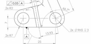
Engineering Drawing and GD&T Seminar discusses the basic rules for creating valid, fully dimensioned engineering drawings defined using the appropriate dimensional and geometric tolerances. The basic aim of the teaching material is for the trainee to understand the details that are involved to the creation of fully defined engineering drawings. Attending the Seminar in scope the trainee is to learn how to understand and create engineering drawings that have been created according to the most recent ISO standards.
Engineering Drawing and GD&T Seminar is the perfect training program for the professionals who are involved to the design and manufacturing sectors and seek for the development or the imrovement of their engineering drawing creation or understanding skills.
The Seminar is divided to two distinctive teaching levels that are presented bellow and analysed at the Engineering Drawing and GD&T Guide:
a. Basic Engineering Drawing
(Duration: 32hours)
The first Level of the Seminar aims to the in depth understanding of the basic Engineering Drawing rules and guidelines according to the International Standards (ISO). After successfully attending the first Level of the Seminar, the trainee will be able to understand and create fully defined and dimensioned engineering drawings.
b. Advanced Engineering Drawing and GD&T
(Duration: 24hours)
The second Level of the Seminar aims to the deeper understanding of the advanced topics that are related to the definition of parts and assemblies specifications on engineering drawings. So, Surface Roughness indication and Geometric and Dimensional Tolerancing ( GD&T) are being dicussed and analysed. Material is thoroughly covered and analysed by demonstrating real engineering drawings as examples. It has to be mentioned that the understanding of the teaching material is crucial for everyone who is involved to the design or manufacturing sector.
Detailed Material of Level a
| Unit | Detailed Description |
| 1st | Essentials of Engineering Drawing:
• Basics of projection geometry and projection of a given part |
| 2nd | Advanced Engineering Drawing Topics:
• Sectional views |
| 3rd | Engineering Drawing of Common Machine Elements:
• Drawing of thread fastening systems (bolts, nuts, washers) |
| 4th | Introduction to best practices of using CAD for the creation of fully defined engineering drawings:
• Commercial CAD systems |
Detailed Material of Level b
| Unit | Detailed Description |
| 1st | Indication of surface texture:
• Essentials of surface texture and roughness |
| 2nd | Dimensional tolerances of parts and assemblies:
• Dimensional tolerances indication |
| 3rd | Geometric tolerancing:
• ISO indication of geometric tolerances |
| 4th | General tolerances:
• General tolerances of dimensional deviations |
| 5th | Application and indication of tolerances using CAD systems:
• Indication of geometric and dimensional tolerancing on 3D MCAD systems |
General Information
- For more information about the Seminar and its organisation, please contact us via e-mail
- Hardcopy of the teaching material is provided for every trainee
- Certificate of attendance is given to every trainee for each of the Seminar Levels
- Special offer (-10% for Level a) applies for group participations

